Diesel Tech Install logo
F350 Soup Instagram
BY COLIN PETERSON
Diesel Tech Install logo
BY COLIN PETERSON
F350 Soup Instagram
The F350 Soup Build
BDS lift kit install on our F350
Diesel Tech Install logo
BY COLIN PETERSON
The F350 Soup Build
BDS lift kit install on our F350
F350 Soup Instagram
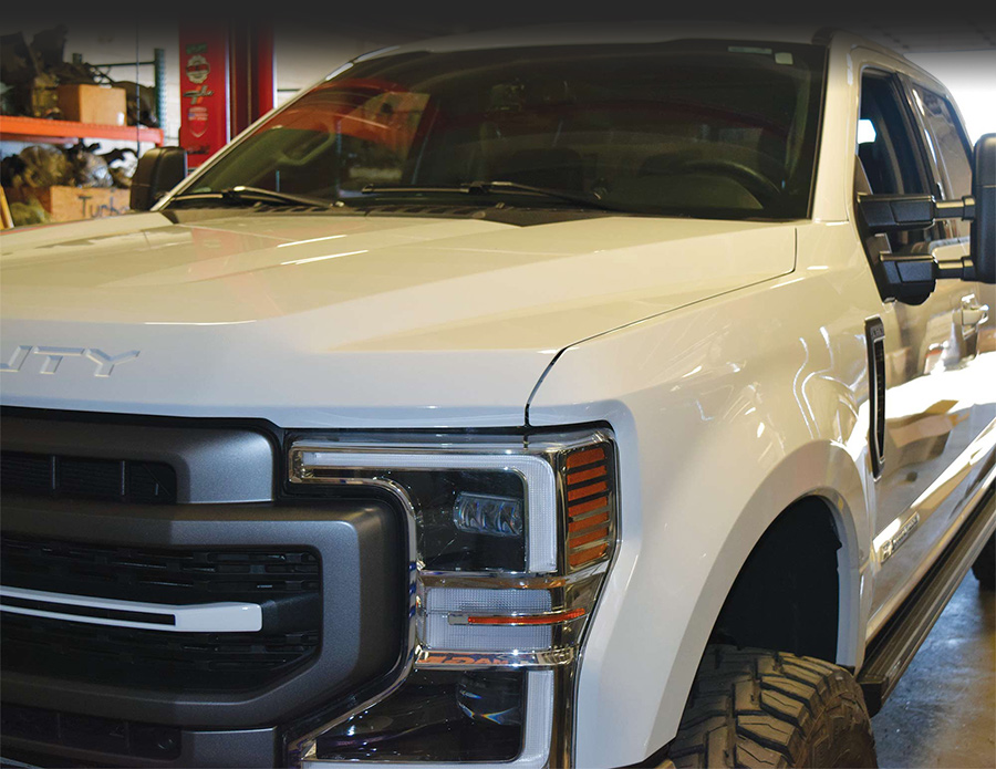
F350 Soup Build in garage
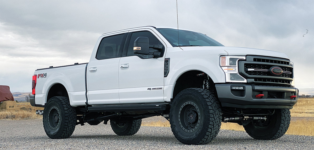
And here we are, on to a big lift kit upgrade on our F350 Soup Build as our latest project truck rolls on. We figured it was time to kick our off-road adventures up a notch, so we added the BDS Suspension Coilover 4-Link 4-inch lift kit on our Power Stroke. This kit brings tried-and-true stability, strength and caster control over factory radius arm setups.

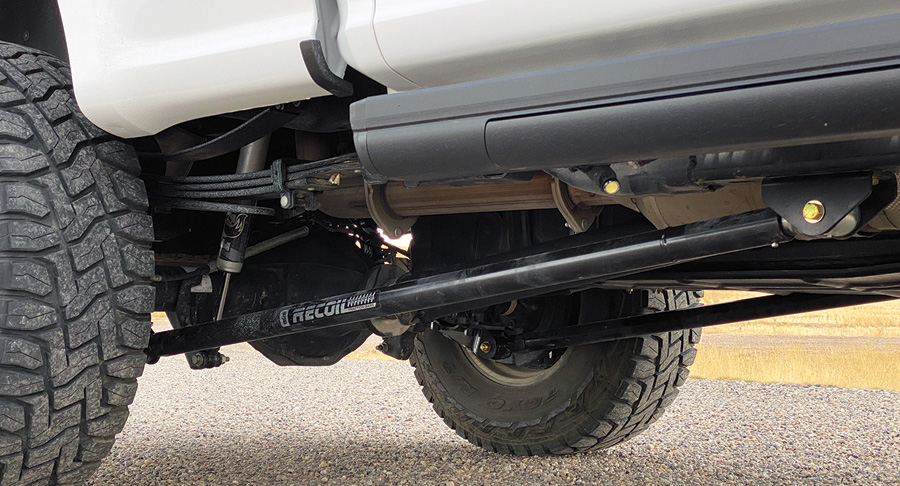
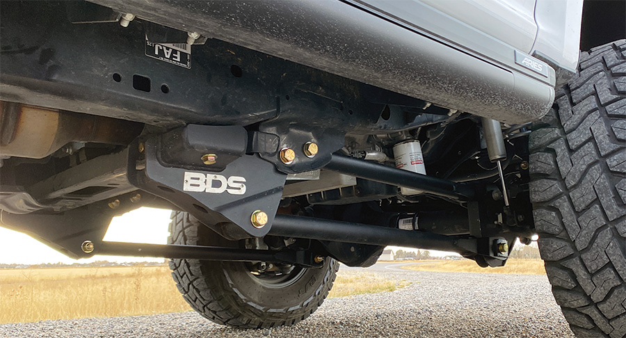
The 4-link brackets are built from 1/4-inch steel, they key off the factory frame bracket and transmission cross member for extra strength, and they utilize heavy-wall 2-inch control arms to correctly position the front axle. The included FOX coilovers also work perfectly for the heavy weight of the 6.7L Power Stroke, and FOX 2.0 IFP performance gas shocks further enhance dampening for a smooth ride on any terrain. With this kit, we’ll be ready for anything. For the installation we returned to our friends at PowerTech Diesel in Idaho Falls, Idaho, where technician Jordan Johnson did the install.
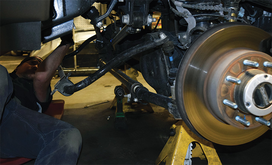
the front end of the F350 with the axle sitting on jack stands
Step 1: Remove Stock Suspension
Jordan jacked up the front end of the F350 with the axle sitting on jack stands. After taking off the wheels and brake line brackets, he began the project by unbolting and removing all the old suspension components, starting with the sway bar and its brackets, followed by the shocks, springs, bump stops, drag link and track bar bracket. With those, he also removed the top spring baskets on both sides of the truck, as they were to be replaced with the new BDS ones.
the new upper basket for the spring on the driver’s side
Step 2: Install Baskets
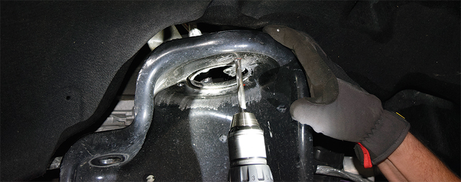
In preparation for the new upper basket for the spring on the driver’s side, Jordan dismounted the ABS module and wiring, moving it away so he wouldn’t penetrate the module when drilling mounting holes in the frame. He positioned the basket so he could mark the holes for drilling. Once that was done, Jordan drilled the holes. He used a smaller drill bit to start the holes (as they start more easily with a fine point) and then used a larger one to finish. With the holes carved out, he inserted a stud into each of them to smooth it out. Some paint was peeled off from cutting off the old basket, so Jordan spray-painted the surrounding frame area before bolting the basket to the holes. After that, the lower basket was installed, replacing the old one. This entire process was then repeated for the passenger side.
driver side radius arm along with the adjacent skid plate
Step 3: Drop Brackets
With the baskets taken care of, Jordan shifted his focus onto the radius arms. He removed the driver side radius arm along with the adjacent skid plate; with it off, he installed the drop bracket for the new four-link radius arm that was to take the old arm’s place and help lift the truck. Before bolting in the bracket, he installed shims between the rear of the bracket and the part of the truck’s frame where it was mounted to provide a buffer between the two. The truck needed to be jacked up slightly so the bracket bolt holes could be aligned. This same process for installing the drop bracket was repeated for the passenger side after removing that side’s radius arm.
Step 4: New Radius Arms
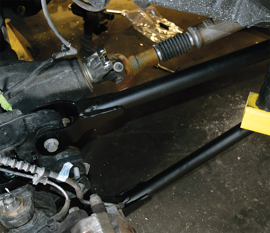
Jordan took the new radius arms out of the box and began assembling them. He then mounted one of the upper (short) arms on the driver side and inserted the bolts in the holes where appropriate without tightening them.

“I leave the bolts loose until all the parts are in place when I can,” says Jordan. “The parts need to establish their position and I want to leave room for error in case adjustments need to be made.” With the new arm in place, he uncoupled the drive shaft from the axle before continuing radius arm work, as it would get in the way. Next, he bolted in one of the lower (long) arms on the driver side. This process was repeated on the passenger side.
the new radius arms out of the box
Step 4: New Radius Arms
Jordan took the new radius arms out of the box and began assembling them. He then mounted one of the upper (short) arms on the driver side and inserted the bolts in the holes where appropriate without tightening them.

“I leave the bolts loose until all the parts are in place when I can,” says Jordan. “The parts need to establish their position and I want to leave room for error in case adjustments need to be made.” With the new arm in place, he uncoupled the drive shaft from the axle before continuing radius arm work, as it would get in the way. Next, he bolted in one of the lower (long) arms on the driver side. This process was repeated on the passenger side.
the new coilovers being installed
Step 5: Coilovers
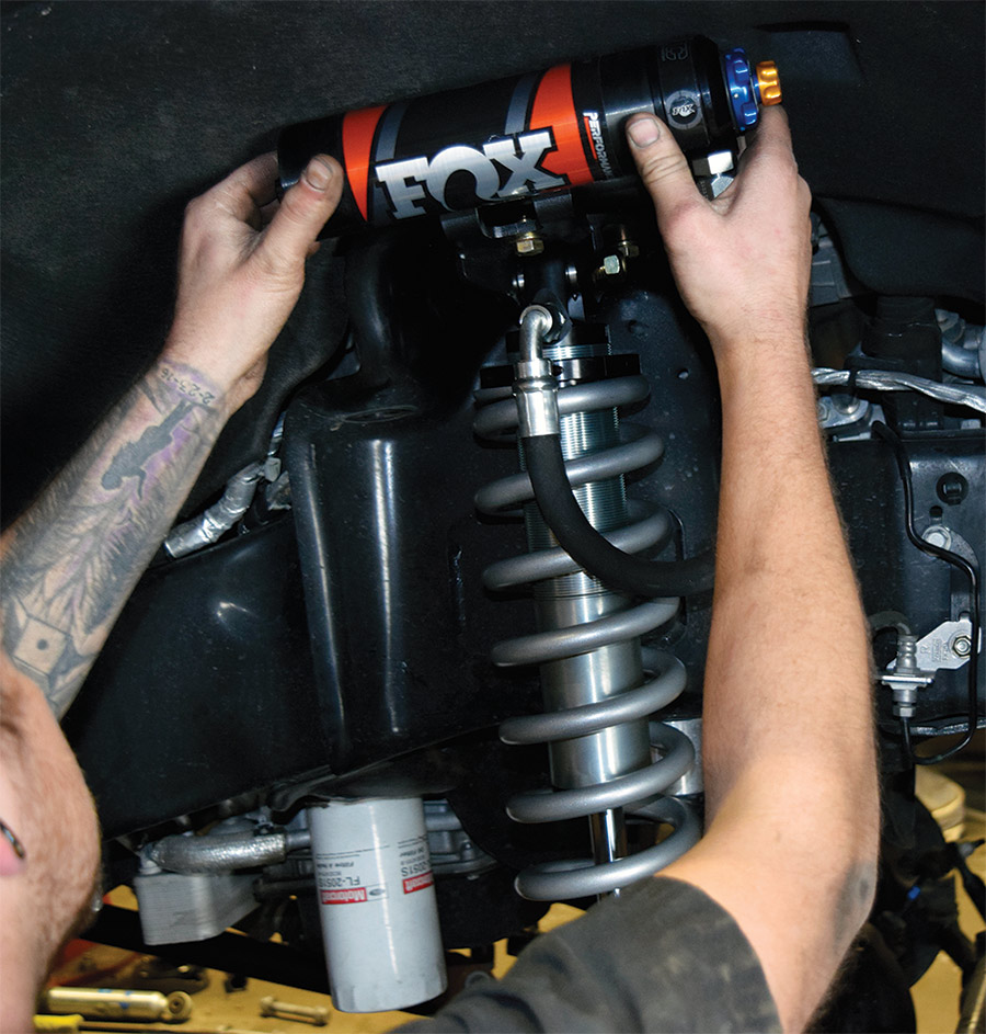
Next, Jordan began to put in the new coilovers, starting with the one on the passenger side. In doing that, he mounted the top bolts and aligned the shock’s bottom holes. He lowered the lift, pushed the bottom of the shock into the basket, inserted the bolt into the hole and then tightened the nut on it. He repeated the process for the driver side after re-affixing the upper mounting basket there.
Step 6: Extend Front End Components
The steering column also needed height compensation for the new lift, so Jordan removed the old Pitman arm drop, replacing it with the new one. He then reconnected the Pitman arm and drag link. The track bar also needed to be compensated, so he installed a new, larger mounting bracket, tightening up five bolts on it. The sway bar then had its lifting blocks installed before being put back together. The track bar subsequently was reassembled. With all other suspension components in place on the front end, Jordan installed the bump stops with the new extensions to compensate for height difference.
steering column needing height compensation
Step 6: Extend Front End Components
The steering column also needed height compensation for the new lift, so Jordan removed the old Pitman arm drop, replacing it with the new one. He then reconnected the Pitman arm and drag link. The track bar also needed to be compensated, so he installed a new, larger mounting bracket, tightening up five bolts on it. The sway bar then had its lifting blocks installed before being put back together. The track bar subsequently was reassembled. With all other suspension components in place on the front end, Jordan installed the bump stops with the new extensions to compensate for height difference.
tightening up bolts around the coilovers
the IFP shocks being installed
Step 7: Install Front Shocks & Stabilizers
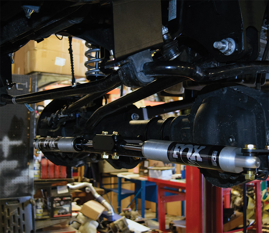
After tightening up bolts around the coilovers, it was time to install the IFP shocks. Before affixing the shocks to the wheel wells, Jordan used a vise grip to push the bushings into the shocks’ bottom mount holes. He then bolted in the driver side shock followed by the one for the passenger side. With those installed, he raised up the truck to install the steering stabilizers. He began that by mounting and installing the brackets for them on the center and ends of the axles. After inserting the bushings into the ends of the stabilizers with the vise grip, Jordan installed the stabilizers by pushing them to align the bolt holes with the brackets.
Step 8: Replace Brake Line Mounting Brackets
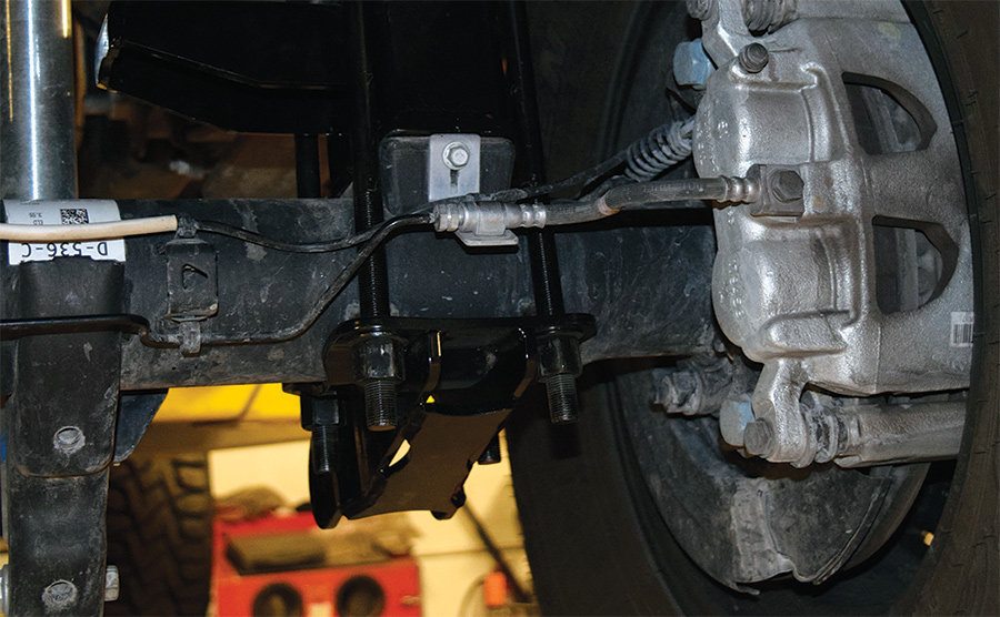
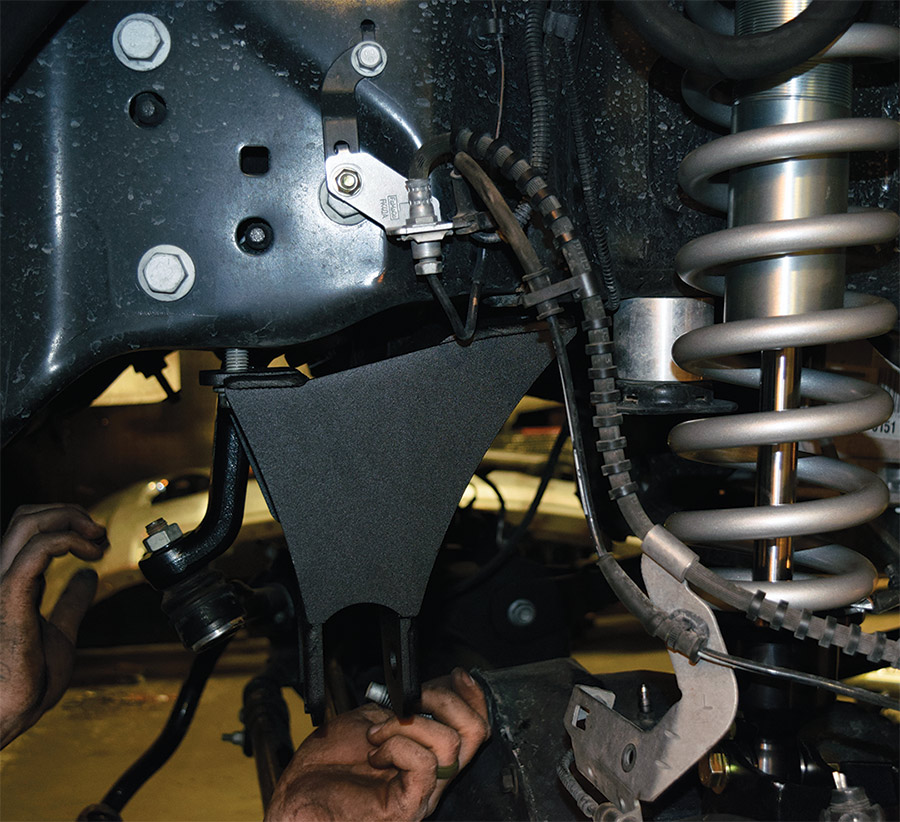
The front end was now mostly complete, except new brake line mounting brackets needed to be installed to compensate for the height difference. Jordan simply remounted the lines in the new brackets after bolting them on, though he had to cut off the old ones. In cutting the old brackets off, he was careful not to cut the lines themselves. He repainted the surrounding area after the pneumatic cutter left a mark with its sparks. With that done, the front end was ready to go back together, so Jordan lowered the lift and put the front wheels back on.
new brake line mounting brackets
Step 8: Replace Brake Line Mounting Brackets
The front end was now mostly complete, except new brake line mounting brackets needed to be installed to compensate for the height difference. Jordan simply remounted the lines in the new brackets after bolting them on, though he had to cut off the old ones. In cutting the old brackets off, he was careful not to cut the lines themselves. He repainted the surrounding area after the pneumatic cutter left a mark with its sparks. With that done, the front end was ready to go back together, so Jordan lowered the lift and put the front wheels back on.
the mechanical work at the truck’s rear end
large U-bolts that secure the air bag brackets
Step 9: Finish Installing Air Bags
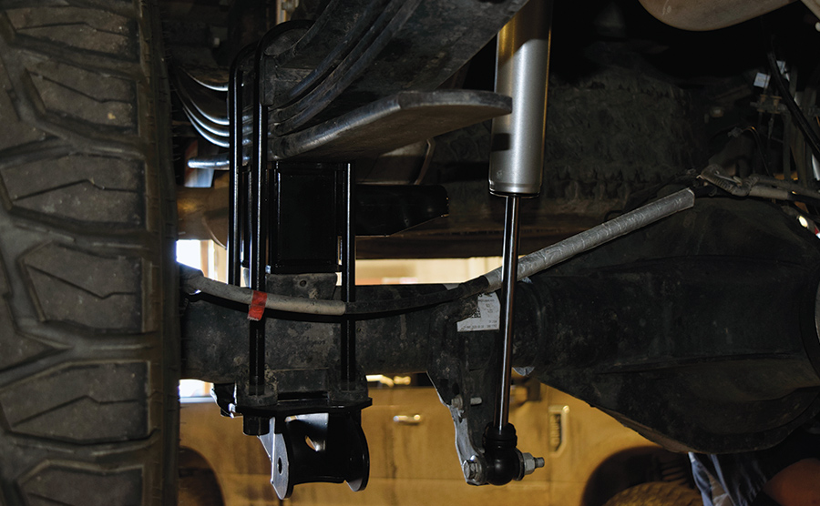
While he was at it, Jordan decided to finish up the mechanical work at the truck’s rear end. He lowered the truck to the ground. The large U-bolts that secure the air bag brackets by wrapping around the axles were not long enough to clear the axles with the small black bars, so he needed to cut same-size threads off other U-bolts and insert them into extensions on the axle threads. With that done, the black bars were inserted and fastened on the studs below the axles.
the wires being inserted
Step 10: Set Up Wiring
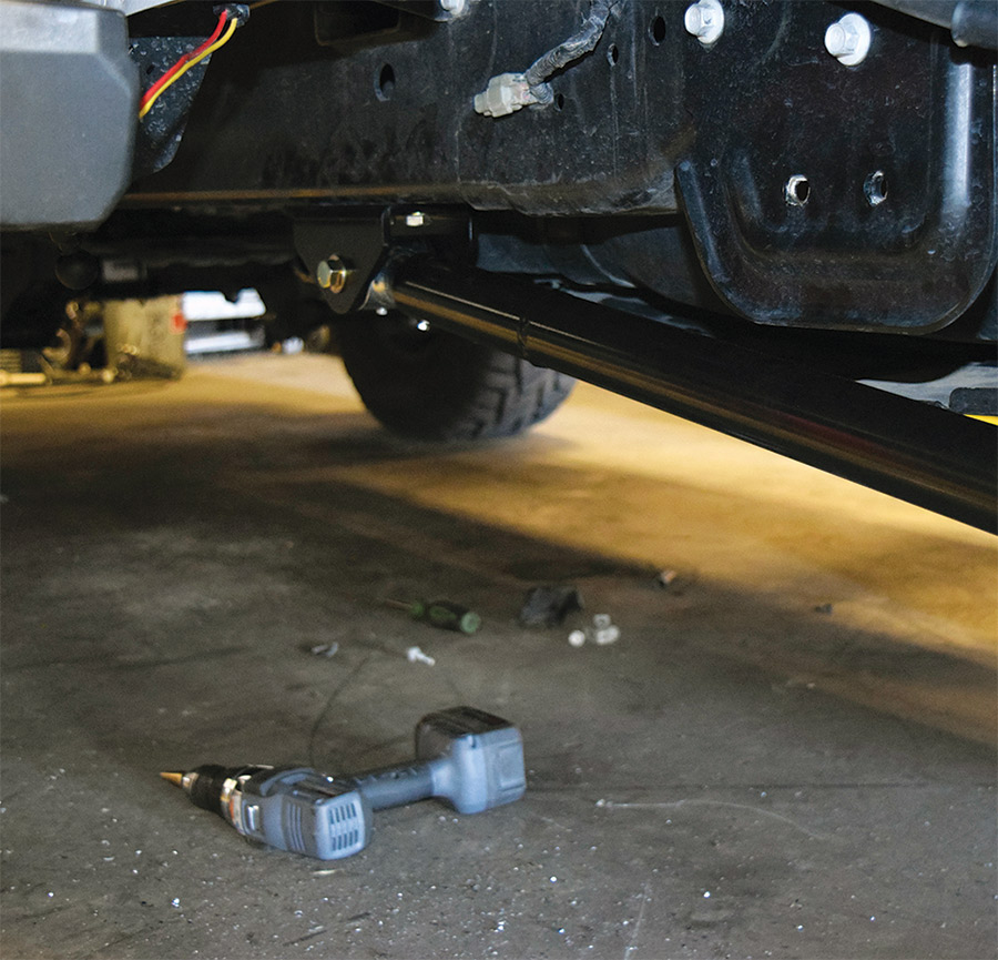
The compressor needed electricity to run, so Jordan started setting up the wires. After lifting the truck up for this job, he inserted the wires into the black looming and then routed them down the passenger side of the frame. He plugged the main control harness into the compressor and spliced the compressor’s ground and power inlets together with the outgoing battery wires. Finishing that part of the wiring up, he zip-tied it to mounts on the frame where appropriate.
power wires up into an opening near the passenger side
Step 11: Connect To Battery
Jordan moved the battery end of the long ground and power wires up into an opening near the passenger side fender and under the hood. He attached a fuse connection onto the live wire just before its end and then connected the ends to the terminals. From the fuse connection, he ran the long pink control wire (already run alongside the power and ground) to a connection on the fuse box.
f350 full body view on road
f350 bds bar underneath the car
f350 recoil bar underneath the car
Sources:
BDS Suspension
517-279-2135
www.bds-suspension.com
PowerTech Diesel
208-542-7793
www.powertechdiesel.com